 The freezer will need to run 24/7, and so I’ll bring my Honda EU2000i generator and refill its gasoline tank throughout the week. To conserve gasoline, the EU2000i has an “Eco-Throttle” mode that keeps the generator in idle. The generator still outputs 115 volts, but at low capacity. When the generator senses a large electrial load it opens its throttle and then the generator can make its rated 2 kilowatts of power.
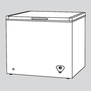
One problem is that the Eco-Throttle gas-saving feature does not work well with compressor motors. When a freezer’s compressor motor switches on, it requires a very large inrush current, but the generator at idle cannot provide it. So instead the compressor motor stalls, and the generator drives the stalled motor at a lower voltage which heats its windings. After the generator revs up, its output voltage rises, and the compressor motor begins spinning. While a compressor motor might survive such repeated mistreatment, I don’t want to risk it failing at Burning Man and causing all of the food to thaw at once.
An idea to address this issue is to create a generator controller. Such a controller would monitor the freezer temperature itself and take the generator out of idle before starting the compressor motor. I’ve done a quick study of the relay ladder logic of old-style industrial process control, and I’ve designed an appropriate circuit. The circuit responds to a high-temperature signal from an external temperature controller by briefly presenting a resistor load to the generator to take it out of idle, and then—after waiting for the generator to spin up—applying full generator power to the freezer. The freezer’s internal thermostat will be set to its lowest temperature to ensure that the compressor motor starts whenever the controller applies power.
While I was designing the circuit, I added another pair of relays to control a second freezer or a refrigerator (in case one is wanted). This circuit ensures that only one appliance runs at a time.
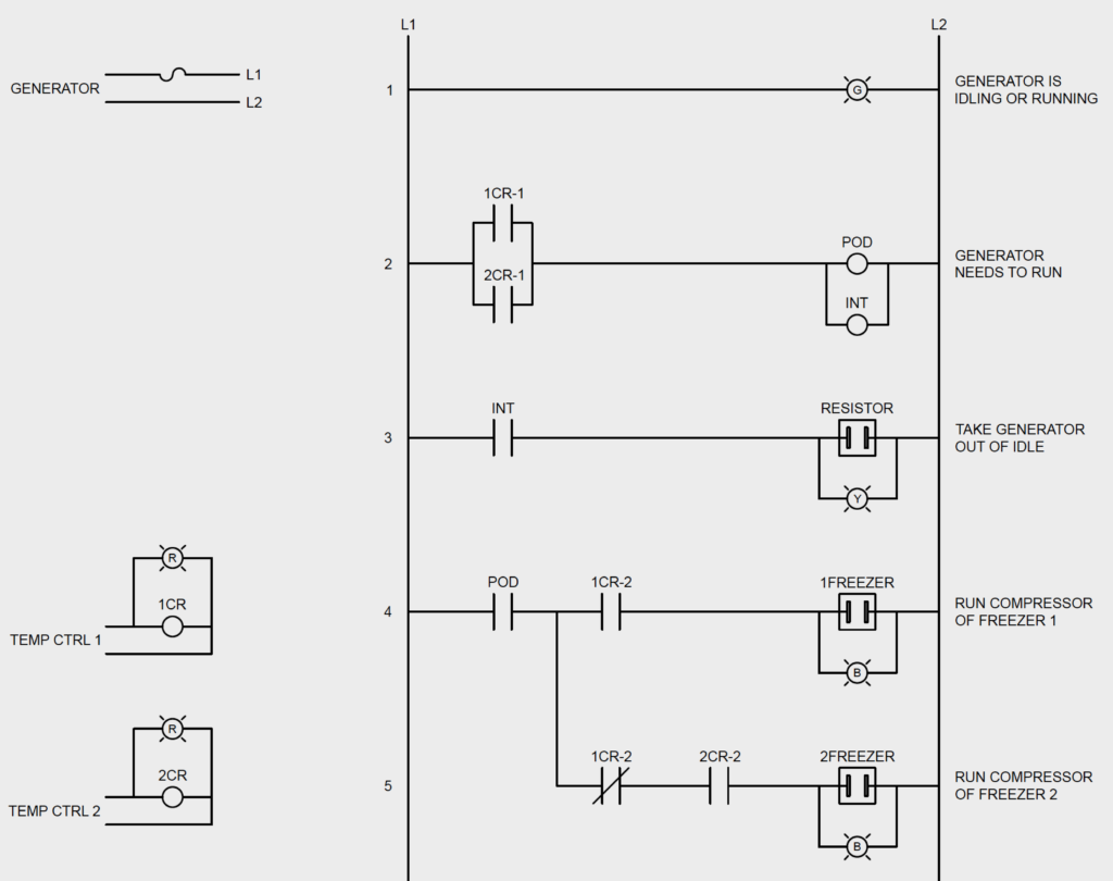
The controller’s diagram is below. Here’s what it means. First, in the upper-left corner you can see that the generator is supplying power to lines L1 and L2 through a fuse. In the lower-left corner you can see that the two temperature controllers drive relay coils and red indicator lamps.
Electrical current flows from L1 to L2 through the rows of the ladder. The rows of the ladder are numbered.
- Row 1 is a green indicator lamp that lights when the generator is idling or running. This lamp always should be illuminated. If it ever extinguishes, that indicates something is wrong with the generator.
- Row 2 energizes two coil relays when either appliance needs to run. 1CR-1 is a pair of relay contacts that closes when the first temperature controller detects a high temperature. Similarly, contact pair 2CR-1 closes when the second temperature controller detects a high temperature. If either of these relay contact pairs closes, then electrical current flows through row 2, and two relay coils POD and INT are energized. The circle marked POD is the coil of a “power-on delay” relay; the circle marked INT is the coil of an “interval” relay. These two timer relays help coordinate the loads on the generator.
- Row 3 is controlled by the pair of contacts of the interval relay. The interval relay closes these contacts for a few seconds when either of the compressor motors needs to start. But the interval relay doesn’t drive the compressor motors. Instead it briefly drives a resistor load to kick the generator out of idle. (Row 3 also has a yellow indicator lamp to show the duration of the interval timer.)
- Row 4 performs relay logic. Freezer 1 receives power (and its blue indicator lamp illuminates) when the freezer’s temperature controller provides a high-temperature signal and the power-on-delay relay has waited for the generator to spin up. The relay logic requires that both of these conditions be true by placing contact pairs 1CR-2 and POD in series in the row. Only when both contact pairs are closed can electrical power reach 1FREEZER.
- Row 5 also performs relay logic. If Freezer 1 doesn’t need to run but Freezer 2 does, then the ladder logic instead applies power to Freezer 2 and its indicator lamp. In this row, the pair of contacts marked 1CR-2 includes a diagonal line. This mark means that the contacts open when coil relay 1CR is energized. This addition to the circuit prevents both freezers from running simultaneously since the ladder logic now requires three conditions to be true before electrical power will reach 2FREEZER: Freezer 2 must need to run, Freezer 1 must not need to run, and the power-on-delay relay must have waited for the generator to have spun up.
If desired at some point, a third load can be added. See the PDFs below.